
Trace Your GMT800's Wiring Before You Bolt In a Second Battery
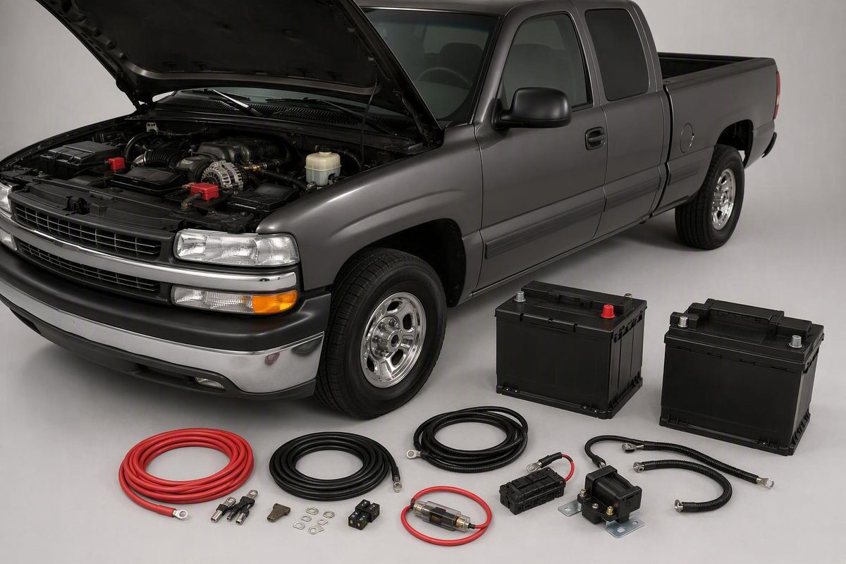
Plan a second battery for a 2000 Silverado: trace the GMT800 wiring, pick parallel or isolated, and see what two documented owner builds actually used.
No factory-approved, model-wide auxiliary battery procedure for the 2000 Chevrolet Silverado turned up in the sources reviewed here; what exists are individual owner installations. The layout that holds up across them is an isolated one: a second battery in a secured tray, a continuous-duty relay or isolator between the two positives, protection at both battery ends of that cable, and a return path designed for the truck. The one documented 2000 Silverado build, a 1500 Z71 with the 5.3-liter, put the battery near the passenger-side firewall and used 2-gauge cable with a 200-amp continuous-duty relay. Those are one truck’s numbers, not a specification, so the job starts with tracing your own wiring and having cable, fuse, and switching ratings calculated for your load.
Pick what you found under the hood, the job for the second battery, and the records you have; the verdict and next steps update beside the selectors.
Aux Battery Planner for a 2000 Silverado
Existing wiring
Single battery. Nothing to work around, but trace the positive and negative cables so the design starts from the real routing.
Architecture to plan
Isolated auxiliary: protection near the starting battery, a properly rated isolator or continuous-duty relay, protection near the auxiliary battery, then separately protected accessory circuits.
Do next
- Identify the alternator from the truck itself and verify its rated output.
- Get each accessory's continuous and peak current from its manufacturer documentation or a technician's measurement.
- Measure the complete positive and return cable routes, not straight-line distance.
Optional: engine-off draw for the design handoff
Amp-hours drawn = continuous amps × engine-off hours.
Enter both values to see amp-hours drawn.
A design input, not a battery size. Usable capacity depends on the battery type and its manufacturer's limits.
What the two documented owner builds reported
| Item | 2000 Silverado 1500 Z71 5.3L | GMT800 Suburban |
|---|---|---|
| Interconnect cable | 2-gauge | 2 AWG |
| Switching device | 200 A continuous-duty relay, ignition-controlled | 200 A isolator |
| Interconnect fuses | Not documented at both ends | 150 A at both ends |
| Alternator | 130 A (as described by the author) | — |
| Battery location | Passenger-side firewall | — |
| Return path | Engine block | — |
| Voltage after install | — | 14.5 V starting, ~14.25 V auxiliary |
Sources: Off-Road.com 2000 Silverado install, TahoeYukonForum owner write-up, GM-Trucks.com thread. Individual owner builds, not GM specifications; do not combine them into a parts list. — = not reported.
The Install Sequence Is Inspect, Design, Mount, Then Test
A 2000 Silverado is a GMT800 truck, and the Silverado generation reference places it there. The generation label does not identify the engine, duty class, alternator, battery wiring, underhood clearance, or a previous owner’s modifications, and that reference carries no electrical specifications.
Work in this order:
- Identify the exact truck, powertrain, alternator, batteries, and added electrical equipment.
- Trace every heavy battery cable and classify the existing arrangement.
- Define whether the second battery is for engine-off accessories, starting assistance, winching, or another specific load.
- Record continuous current, surge current, operating time, cable length, charging demand, and acceptable voltage drop for the design.
- Verify tray fit, restraint, terminal clearance, cable routing, and the proposed return path.
- Select components only after their ratings have been matched to the verified design.
- Test isolation, charging behavior, voltage drop, and temperature under the intended load.
Stop work if you find undocumented aftermarket wiring, cannot identify the alternator, cannot explain an existing cable or brace, cannot inspect both sides of a proposed drilling point, or lack the equipment and instructions to terminate heavy-current cable. Those are jobs for a qualified automotive electrician.
The documented 2000 Silverado installation warns that batteries can explode and instructs installers to wear eye protection and remove rings, bracelets, necklaces, and other jewelry. Follow an electrical isolation procedure appropriate to the exact truck before starting. Read the warning in the historical Off-Road.com installation.
Trace Every Heavy Cable Before Buying Parts
Fill in this worksheet before buying a battery, tray, isolator, fuse holder, or cable.
| Item | What to record |
|---|---|
| Truck identity | VIN, duty class, cab, drivetrain |
| Powertrain | Engine and relevant equipment |
| Charging system | Alternator ID and verified rated output |
| Build information | All glove-box RPO codes |
| Existing batteries | Quantity, location, type, condition, cable routing |
| Added equipment | Snowplow, winch, camper, audio, lighting, inverter, radio, trailer wiring |
| Intended loads | Each device’s documented continuous and peak current |
| Operating goal | Engine-off runtime, accessory reserve, starting assistance, or winching |
For a design handoff, add photos of both battery areas and every heavy-cable connection, measurements of the complete positive and return cable routes, manuals or data sheets for each accessory, the engine-off operating time you want, and current instructions for the proposed battery, isolator or relay, fuse holders, and cable. Write down what should happen with the key off, during starting, and with the engine running.
Do not classify the system from battery count alone. Follow every heavy positive cable until you know whether it reaches the starter, a common junction, another battery, a relay, a solenoid, or an isolator, then trace the negative cables and bonding paths. Participants in an enthusiast thread about a dual-battery Silverado recommend the same tracing because they reported both direct and isolated arrangements. See the GM-Trucks.com cable-tracing discussion.
| What you find | Classification | Next step |
|---|---|---|
| Positives joined directly or at an always-live junction | Apparently parallel bank | Document the full route; get a design review |
| Relay, solenoid, or isolator between batteries | Isolated or controlled | Identify the device, ratings, control logic, operating state |
| Altered, damaged, or unclear routing | Unknown | Stop; get an electrical inspection |
An alternator rating reported for somebody else’s Silverado does not establish the rating of yours. Read it off the truck.
RPO Code TP2 Is a Lead, Not Proof of Factory Dual Batteries
One participant in that forum thread associated RPO code TP2 with a dual-battery installation, but the thread provides no GM documentation confirming it, and it contains conflicting accounts of whether both batteries assist starting.
Verify the code through authoritative documentation that applies to the VIN, then inspect the truck itself. Previous owners may have changed or removed wiring and components.
Parallel Banks Share Every Load; Isolated Batteries Protect Starting
“Dual battery” describes two different architectures.
| Architecture | Engine-off behavior | Purpose |
|---|---|---|
| Permanently parallel | Both batteries stay connected as one bank | Shared capacity for a deliberately designed common load |
| Isolated auxiliary | Batteries separate when the control system commands it | Accessory reserve that preserves the starting battery |
An isolated arrangement suits camper equipment, lights, communications gear, or audio that should not draw from the starting battery. With no isolating device, engine-off accessory use pulls from the whole connected bank.
The architecture follows from six answers: the maximum continuous current, the maximum surge current, how long the equipment must run with the engine off, whether the auxiliary battery must assist with starting or winching, when the batteries should connect (key-on, only after charging voltage appears, or another defined condition), and what must happen if the control device or charging system fails. For the runtime figure, amp-hours drawn equals continuous amps multiplied by engine-off hours; that is a design input, not a battery size.
Third-party examples show two control approaches. The historical Silverado build used an ignition-controlled relay, while a personal technical write-up describes a voltage-sensitive relay that responds to charging voltage. Neither source establishes a universally correct method for a 2000 Silverado. The choice depends on the truck’s verified charging behavior, the intended operating sequence, and current instructions for the selected device.
An Isolated Auxiliary Battery Does Not Automatically Help Start the Truck
The GM-Trucks.com discussion describes an isolated arrangement in which the auxiliary battery received charging voltage while the engine ran but did not assist with starting.
Do not improvise a bridge between batteries. If starting assistance is required, include it in the original design and have every part of that current path specified for it.
The Accessory-Reserve Layout Runs Fuse, Isolator, Fuse
For planning, an isolated accessory-reserve system reads like this. From the starting-battery positive, the cable runs to a protective device mounted near that battery, then to a properly rated isolator or continuous-duty relay, then to a second protective device near the auxiliary battery, and finally to the auxiliary-battery positive. Accessory circuits leave the auxiliary battery through their own separate protection.
The return side gets the same attention. The auxiliary-battery negative connects through a designed return path to the truck’s bonding and return system, which ties back to the starting-battery negative.
A direct-parallel arrangement is simpler and different: positive to positive, negative to negative, nothing between them.
That description deliberately omits cable gauge, fuse rating, relay rating, control source, terminal torque, and ground location. Those values come from the completed electrical design and the current instructions for the selected components.
Two of the Reviewed Builds Fuse Both Battery Ends of the Interconnect
A personal dual-battery design article recommends fusing the inter-battery positive cable at both battery ends, protecting exposed positive terminals, securing the battery, guarding cables against abrasion, and using grommets at metal pass-throughs. That article concerns a Mazda, not a Silverado, and is not a recognized standard, so treat its points as conservative design considerations to confirm with the electrician and component instructions. Review the dual-battery design example.
One GMT800 Suburban owner installation shows the same arrangement with a fuse at each battery. See the owner’s dual-fuse layout.
Neither source is GM documentation, so the final protection layout, device type, rating, and location should be confirmed through a qualified design. Do not copy the 150-amp fuses from the Suburban example; that value belonged to one owner’s cable, alternator, route, and component choices.
Cable, Fuses, Isolator, and Alternator Are Sized as One System
The reviewed material does not support one cable gauge, fuse size, or isolator rating for every 2000 Silverado, and it contains no Silverado-specific calculation.
| Design input | Information to verify |
|---|---|
| Current and duty | Charging current, continuous load, peak load, operating time |
| Conductors | Full route length, installed ampacity, insulation, terminations, acceptable voltage drop |
| Charging system | Alternator ID, rated output, existing loads, charging behavior |
| Components | Battery characteristics; fuse, holder, and switching-device ratings |
Use measured route length, not straight-line distance. Get accessory current from current manufacturer documentation or a qualified technician’s direct measurement. Get conductor, fuse-holder, relay or isolator, and battery limits from their manufacturers. Do not derive spare alternator capacity by subtracting guesses about the truck’s normal loads.
Historical examples, not a combined specification
The documented 2000 Silverado build reported 2-gauge cable and a 200-amp continuous-duty relay. A separate GMT800 Suburban owner reported 2-AWG cable, 150-amp fuses at both ends, and a 200-amp isolator. These are records of two individual installations, not values to combine into a Silverado shopping list.
Hold off on battery group, capacity, and chemistry until physical fit, terminal orientation, charging compatibility, temperature exposure, cycling duty, and required current have been checked against the design.
Tray Fit, Braces, Drilling Points, and Grounds Are Truck-Specific
The Off-Road.com article documents an auxiliary battery near the passenger-side firewall of a 2000 Silverado 1500 Z71 with a 5.3-liter engine. That establishes where the author placed it on that truck. It does not confirm clearance or mounting provisions on other powertrains and duty classes.
Before approving a location, document tray compatibility with the truck and the selected battery, restraint in every direction, hood and surrounding-component clearance, terminal orientation and positive-terminal protection, access for inspection and replacement, and the full positive and return cable routes.
Do not remove a brace because an owner article did. The historical Silverado installation removed supports to make room, and the GMT800 Suburban writer expressed uncertainty about one brace. Neither establishes that removal is acceptable on another truck.
Inspect both sides of any spot before drilling. The Silverado article drilled at a firewall feature found on one truck and installed a grommet, and it acknowledged the same feature might not appear on another vehicle. Its firewall dimple is not a drilling template. The same author routed the main positive cable along the firewall to avoid heat and possible damage.
Heavy-cable terminals need tools matched to the conductor and lug. The personal design article reports hiring an automotive electrician to install its large ring terminals because specialized equipment was needed. Follow the terminal manufacturer’s current method, not the improvised vise compression or tape-covered work shown in an owner build.
The example installations used both an engine-block return and a chassis return. That disagreement is the reason neither counts as a universal Silverado ground point. The return path is selected and tested as part of the truck-specific design.
Installation Order After the Design Is Verified
Use this order only once the truck, design, components, connection points, and ratings are confirmed.
- Make the truck electrically safe. Follow the vehicle and component procedures, wear eye protection, remove jewelry, and keep disconnected positive conductors off grounded metal.
- Confirm the mounting plan. Recheck tray fit, restraint, hood clearance, terminal protection, and both sides of every proposed hole.
- Install the tray and mounting hardware. Leave unidentified supports in place.
- Mount the switching and protective devices in the locations the design specifies, following current instructions.
- Route cables while they are unenergized. Add the specified supports, pass-through protection, abrasion protection, and heat clearance.
- Make the specified terminations with the conductor, lugs, tools, sealing method, and fastener practices their manufacturers require.
- Connect the designed return path and control circuit. Verify the control source in every relevant key and operating state.
- Inspect before energizing. Check polarity, exposed positive metal, cable support, terminal security, and interference.
Do not copy the named ignition-fuse position or add-a-circuit used in the GMT800 Suburban example; it documents one owner’s choice, not a verified control source for a 2000 Silverado. The older Silverado article’s lack of documented protection at both ends is likewise not evidence that the protection can be left out.
Commissioning Checks: Isolation, Charging, Voltage Drop, and Heat
Commission the installation against its documented design and the component instructions, not against another owner’s voltage readings.
- Engine off: the switching system provides the intended separation.
- Accessory operation: the isolated load runs without drawing from the starting-battery side.
- Engine running: the switching device changes state as intended and the auxiliary battery receives charging voltage.
- Designed load: Have voltage drop checked across the complete positive and return paths under the intended operating load.
- Temperature: cables, lugs, protective-device holders, return connections, and switching-device terminals show no unexpected heating.
- Mechanical condition: battery restraint, terminal covers, cable supports, grommets, abrasion protection, and clearance from heat and movement all hold.
- Operating sequence: engine-off, starting, engine-running, and accessory-use states behave as the design says.
The GMT800 Suburban owner reported 14.5 volts at the starting battery and about 14.25 volts at the auxiliary battery after installation. Those figures describe that vehicle at that moment; the write-up provides no load test, charging-current measurement, or long-term validation.
Stop using the auxiliary system if it does not isolate or charge as designed, if voltage-drop results fall outside the documented design limits, or if connections become unexpectedly hot. Have it inspected before returning it to service.
What the Documented 2000 Silverado Build Proves
The Off-Road.com article reports an auxiliary-battery installation on one 2000 Silverado 1500 Z71 with a 5.3-liter gasoline engine. The author described a 130-amp alternator, a passenger-side battery location, a 200-amp continuous-duty relay, 2-gauge cables, an engine-block return, and an ignition-controlled battery manager.
That demonstrates the architecture of one relay-isolated owner installation. It does not establish compatibility with every 2000 Silverado configuration, and it is not Chevrolet service information.
Its named products may now be obsolete or unavailable, and the article does not document dedicated high-current protection at both ends of the battery interconnect. It is not a current parts list, a drilling template, an approved ground specification, or a complete circuit-protection design. Use it to understand the general architecture, and get the dimensions, locations, and ratings from a design done for your truck.